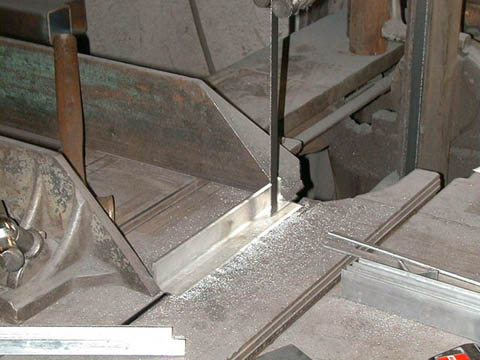
 First, some parts are cut to shape using a band saw.
(photo date July 29, 2000)
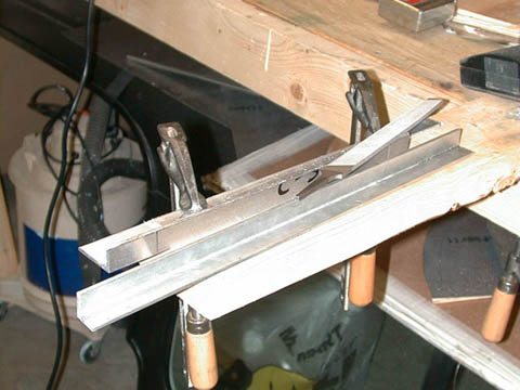 Next, the part is filed smooth then sanded. It is important that all "tool marks" are removed from aluminum parts.
(photo date July 30, 2000)
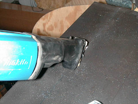 The wheel forks are cut from some very heavy plate steel using a reciprocating saw and metal-cutting blade.
(photo date January 14, 2001)
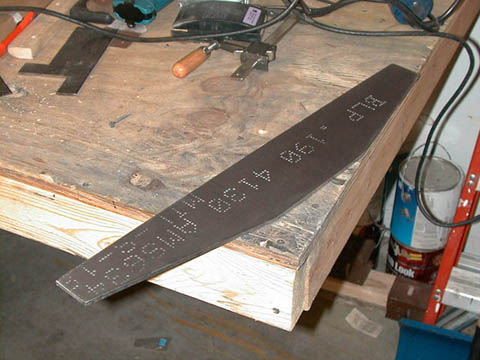
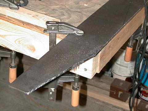 The wheel forks are then rough-shaped with an angle grinder.
(photo date January 14, 2001)
 Now the wheel forks are then finished using files and sandpaper.
(photo date January 14, 2001)
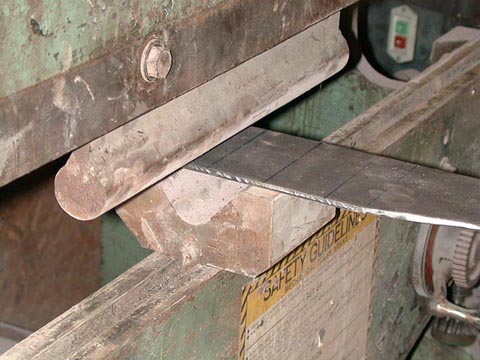 Next, The wheel forks are bent to shape using a press brake.
(photo date April 22, 2001)
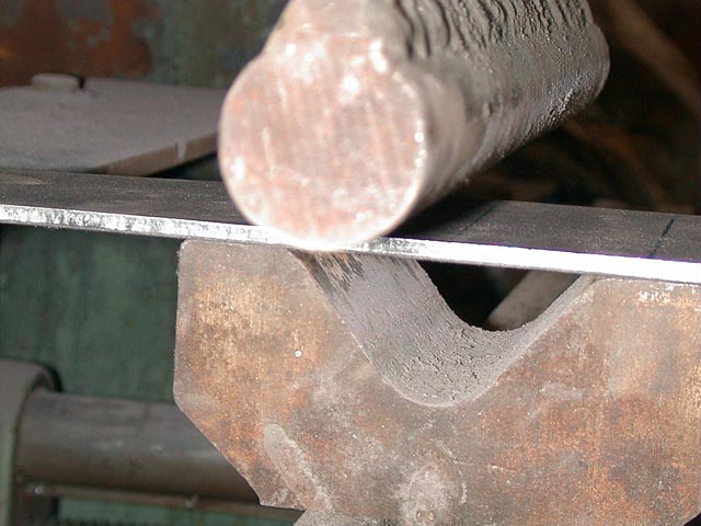 Large radiused press brake dies are used on the wheel forks to keep the thick metal from cracking.
(photo date April 22, 2001)
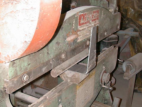 The forks are now positioned in the brake for the second bend.
(photo date April 22, 2001)
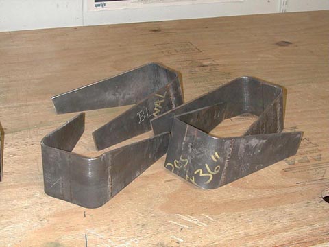 The wheel forks are now ready to be drilled.
(photo date April 22, 2001)
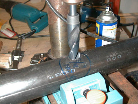 The legs for the landing gear are drilled in a drill press.
(photo date March 11, 2001)
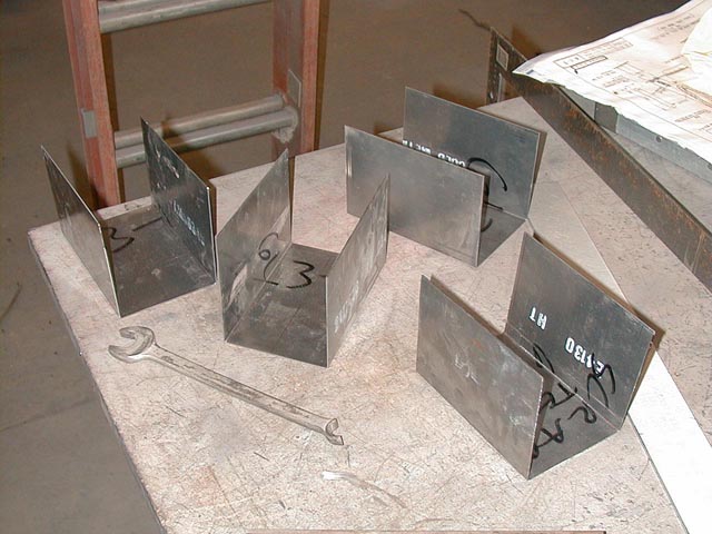 The landing gear bearing boxes are made from heavy sheet steel then bent in a press brake.
(photo date April 22. 2001)
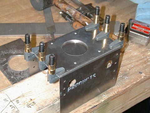
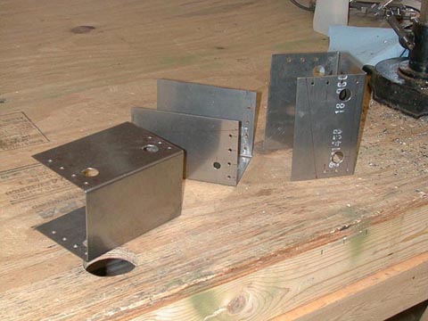 Next, the bearing boxes' bolt holes are drilled.
(photo date April 22, 2001)
 The large hole for the landing gear leg must be rough cut using many small holes, then filed smooth.
(photo date April 22, 2001)
 The landing gear bearings are laid out onto heavy aluminum plate.
(photo date April 8, 2001)
 The landing gear bearings are trial fitted using clamps and clecos before drilling.
(photo date April 8, 2001)
 The landing gear bearings' final shape are sawn from the aluminum blank.
(photo date April 8, 2001)
 The landing gear bearings are carefully fitted to the bearing box.
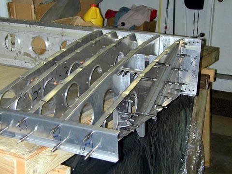 The landing gear box is fitted into the center wing section skeleton.
 The landing gear tube leg with bungee cord "shock absorbers" is assembled and installed in the wing.
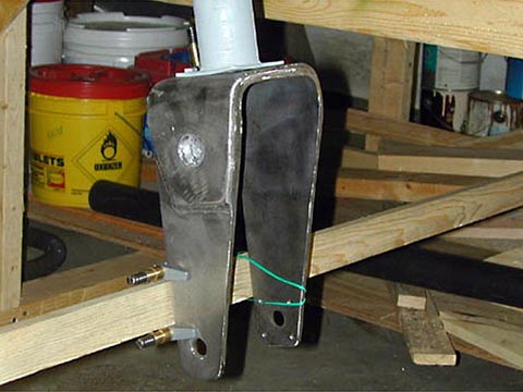 The landing gear wheel forks are aligned with each other before they are drilled to match the gear legs.
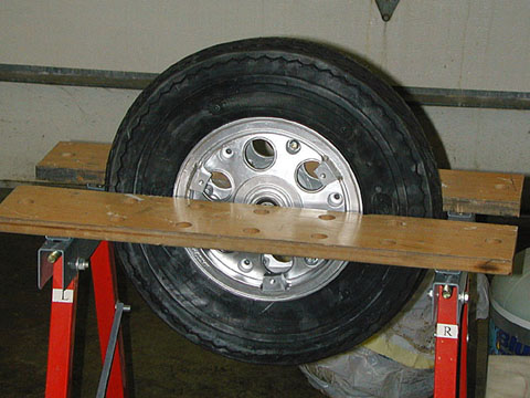 The tubes are inserted into the tires, then the wheels are bolted together.