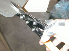
 Most sheet aluminum parts are cut out using metal snips. Usually, gloves are worn to protect the hands. Here, my fingers are protected with duct tape.
(photo date June 10, 2000)
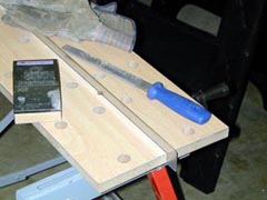 Many pieces are made from simple "L" angles, formed from light sheet aluminum. Here a freshly cut piece of aluminum is being filed and sanded just before bending.
(photo date October 21, 2001)
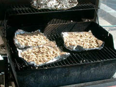 When tubes are bent, they are often filled with sand to keep them from collapsing. Dry sand flows more smoothly, so here I am drying sand by heating it in a barbecue grill.
(photo date March 18, 2001)
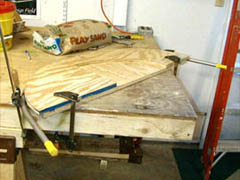
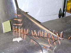
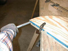 The tubes are filled with dry sand and bent around plywood form blocks.
(photo date March 18, 2001)
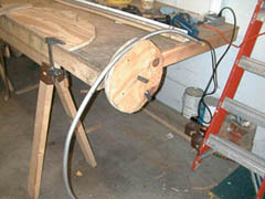 Sometimes the tubes must be rolled around a plywood wheel to get a little "extra" bend.
(photo date March 31, 2001)
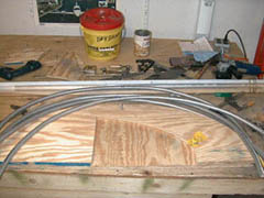
 The bent tubes are carefully checked against the form blocks.
(photo date March 18, 2001)
 The bent tubes are cut to their final size.
(photo date March 31, 2001)
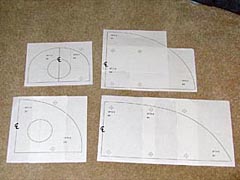 The bulkhead shapes are drawn using computer coordinates then printed. The prints are taped together and are traced onto the plywood for the form blocks.
(photo date February 8, 2001)
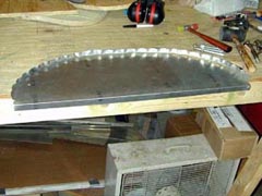 The bulkheads are formed over their form blocks just like the ribs.
(photo date December 11, 2001)
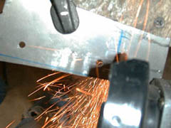 Small steel parts are usually cut out with a saw, but sometimes grinding is the only way to shape them.
(photo date April 7, 2001)
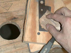 Once ground to shape, the part is then sanded.
(photo date March 31, 2001)
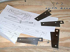 The sanded parts are checked against the plans for accuracy.
(photo date March 31, 2001)
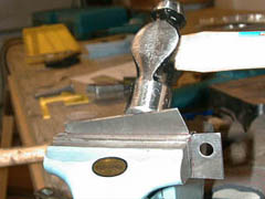 Too thick for the hand brake and too small for the press brake, sometimes parts have to be bent by hammering them over while clamped in a vice.
(photo date April 7, 2001)
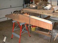 The thick, extruded aluminum longerons are bent across a plywood form block to the proper shape.
(photo date October 19, 2000)
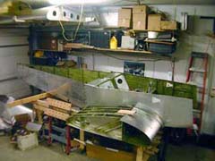
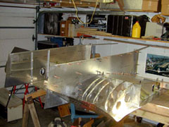 The forward section of the fuselage is built over the center wing section.
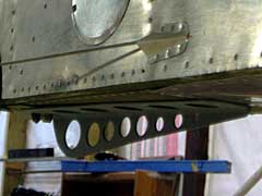
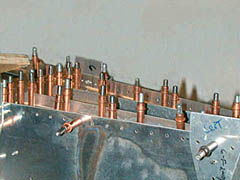 The brackets for connecting the horizontal stabilizer are attached to the rear fuselage.
 The rudder hinges are fitted to the rear fuselage.
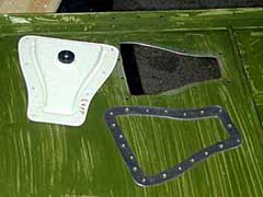 The fresh air vents are fitted to the forward fuselage. A thick shim is made to allow the vents to fit flush to the fuselage.
 The front and rear fuselage parts are joined together.
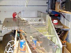 The alignment of the fuselage is checked.
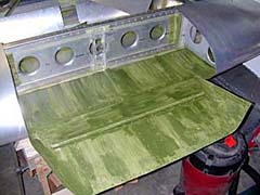 The front fuselage floor is installed.
 Fairings are shaped from light-gauge aluminum and are fitted to the fuselage.
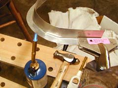 The flange from an aluminum angle is heated so that it can be stretched to wrap around the wing joint.
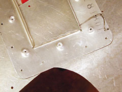 Access holes for maintenance are built into the front fuselage. Oversize rivets are pressed into the backing plate, drilled and then tapped for 6-32 machine screws.
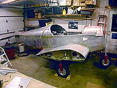 At last, the fuselage is lifted off the work table and is on its own wheels. Next step: to the airport for final assembly.
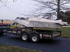 The airframe is loaded on the trailer and being moved to the airport.
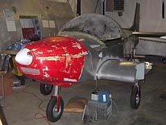 The cowling is fitted to the fuselage and installed.
 The tiedown ring is removed and a combination tailskid and tiedown is fabricated from steel and installed..