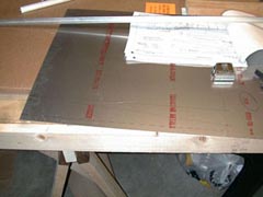
 Like all sheet metal parts, the part is drawn onto the metal using a sharp felt-tipped pen.
(photo date May 27, 2000)
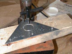 Some parts are made in a drill press. Here, a large lightening hole is cut into the thick metal of a bellcrank using a fly cutter.
(photo date October 4, 2000)
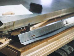
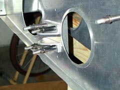
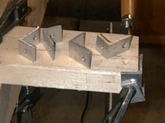 Small parts are cut from extruded aluminum angle. These parts are then clamped or screwed to a scrap board for final shaping and sanding.
(photo date August 8, 2000)
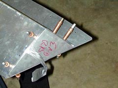
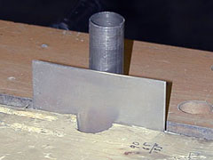
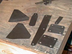 Some control parts are made from plate steel.
(photo date January 13, 2001)
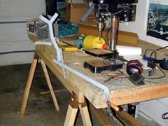 The main control stick and torque tube are made from steel tube then welded together.
(photo date March 12, 2002)
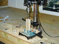 Nice, wooden hand grips for the control stick are made from scrap oak table legs. Here they are drilled in a drill press using a forstner drill bit.
(photo date February 19, 2002)
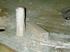 The wooden hand grips are shaped using carving knives and a belt sander.
(photo date February 19, 2002)
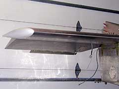
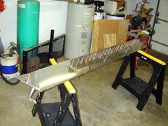 The aileron is made from sheet aluminum just like a wing.
(photo date April 14, 2002)
 The end rib is fitted to the aileron. Sometimes duct tape is used as a third hand to hold parts!
 The aileron control horn is fitted to its rib.
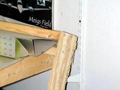 If the wing must be ratchet-strapped after the aileron is installed, special braces must be rigged from scrap wood to keep from damaging the aileron.
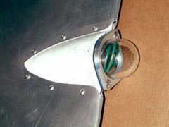 The rudder is made just like the ailerons. Here, the tail light is installed into the rudder.
 The aileron bellcrank brackets are fitted to the center wing section.
 Attachment brackets for the toe brake master cylinders are made from heavy aluminum sheet, then are bent around a tube.
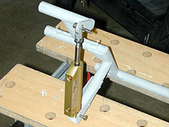 The brackets are riveted to the pedal assemblies, then the brake master cylinders are bolted into position.
 The elevator is riveted to the horizontal stabilizer.